Guide
What to Prepare Before a 3D Scanning and Reverse-Engineering Project
Prepare a 3D scanning enquiry with the right photographs, dimensions, access details, reference data, required outputs, and engineering objectives.
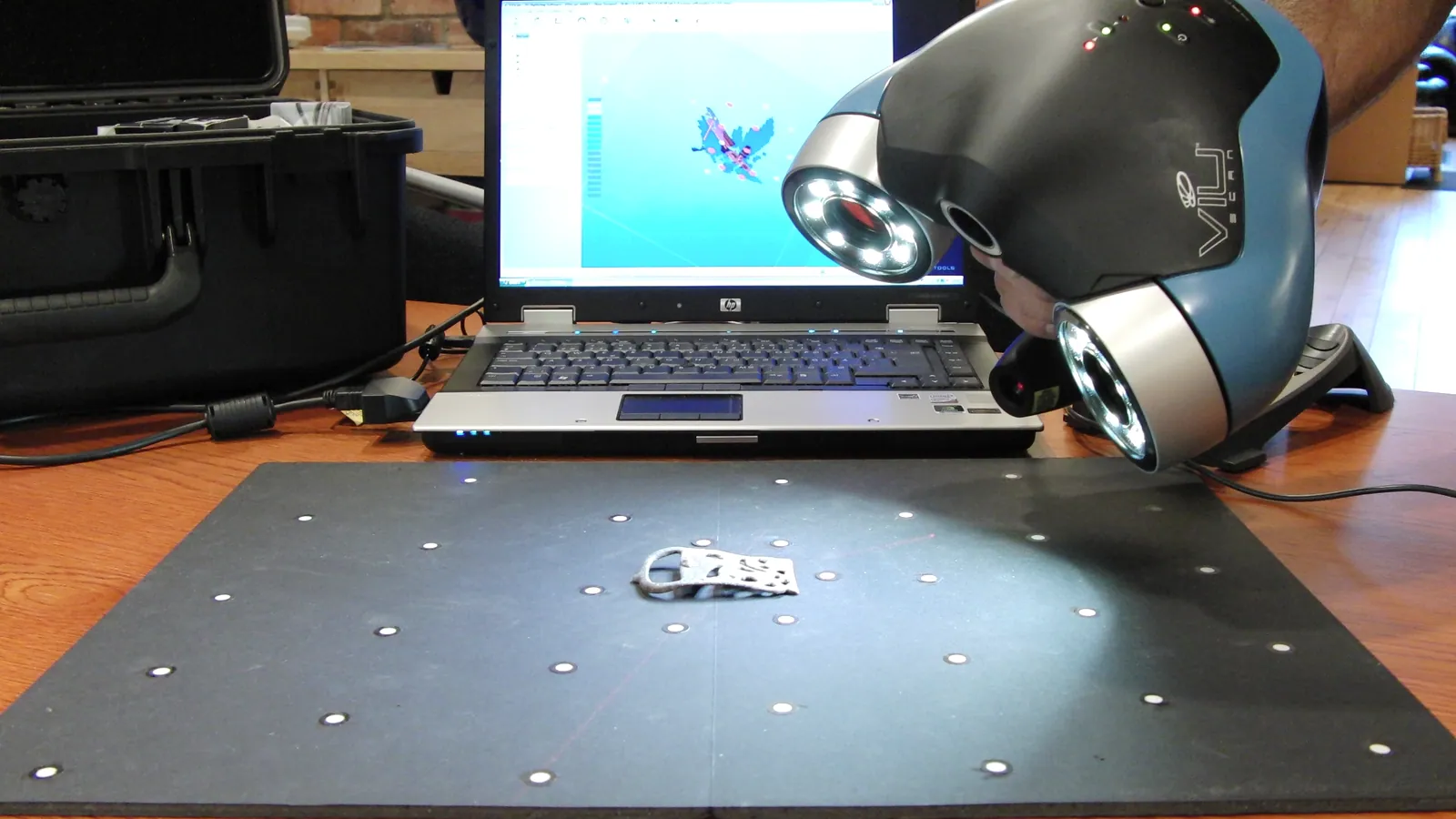
A useful 3D scanning enquiry begins with the problem that needs to be solved, not with a request for “a scan.” The same physical component could be captured for documentation, comparison, CAD reconstruction, redesign, inspection planning, packaging, or a possible replacement. Each objective changes the information, access, measurement, interpretation, and review that may be required.
Good preparation does not mean producing a complete technical specification before speaking to a provider. It means sharing enough reliable context to decide whether scanning is suitable, what other evidence may be needed, and what the project should deliver.
This checklist will help you prepare that first discussion without assuming an equipment model, file format, accuracy, price, or turnaround before the part and objective have been reviewed.
1. Define the decision the project must support
Begin with a short statement describing what you need to decide or do after the work is complete. For example:
- document the current external geometry of an existing component;
- recreate editable CAD where the original model is missing;
- compare a physical part with an existing CAD model;
- understand a mating envelope before redesigning an assembly;
- investigate wear, distortion, damage, or an unexpected fit;
- prepare engineering information for a possible replacement part.
Avoid describing the deliverable only as a scan, mesh, or model. Those are possible forms of data, not the business outcome. A provider needs to understand who will use the information and what decision it must support.
If the goal is a replacement component, explain whether you want to reproduce the current condition, recover likely nominal geometry, or redesign part of it. A worn component may be valuable evidence, but copying every worn surface is rarely the same as recovering the intended design.
2. Send clear photographs
Photographs can reveal geometry, condition, access, and scale before anyone handles the part. Include:
- an overall view from several sides;
- close-ups of complex, damaged, reflective, or important areas;
- mounting points, bores, flanges, threads, mating faces, and other interfaces;
- hidden or obstructed areas where possible;
- the surrounding machine or assembly if the part cannot be removed;
- a ruler or another clearly stated scale reference in at least one image.
Do not rely on one close-up that makes the part appear larger or simpler than it is. Keep the original image files where possible, as messaging applications can remove detail or metadata.
Mark up a copy of the photographs if particular regions matter. A simple arrow labelled “critical mating face” or “damage in this area” can prevent a misunderstanding during the first review.
3. Provide approximate dimensions and handling information
State the approximate overall length, width, height, and weight. Exact values are not required for an initial enquiry, but the difference between a hand-held component and a machine structure changes transport, access, handling, and capture planning.
Also explain:
- whether the part can be lifted safely by one person;
- whether lifting equipment, access platforms, or permits are required;
- whether it is loose, fixed, installed, or still connected to other equipment;
- whether it can be rotated or repositioned;
- whether delicate, flexible, sharp, hot, contaminated, or hazardous conditions apply;
- whether production or maintenance activity limits the available access window.
For a site-based discussion, include the location within the facility, working clearance, lighting, power restrictions, induction requirements, and any rules governing photography, surface preparation, or data capture.
4. Explain whether the part can be moved
A supplied part can often be reviewed from more positions and under controlled conditions. An installed part may need to be captured around obstructions, guarding, adjacent equipment, or restricted working areas.
If the part cannot be removed, explain why. It may be too large, too fragile, operationally critical, difficult to realign, or unavailable outside a planned shutdown. Include photographs of the access route and working space, not just the component itself.
Triaxis can discuss scanning at a customer’s site or from a supplied part, subject to reviewing the requirement. This is a planning discussion rather than a promise that every location, component, or access condition is suitable.
5. Share existing drawings, CAD, and records
Even incomplete or outdated information can be useful if its status is clear. Relevant material may include:
- drawings and their revision history;
- native CAD, neutral CAD, meshes, or previous scan data;
- manuals, catalogues, assembly diagrams, or spare-parts lists;
- inspection reports and previous measurements;
- material certificates, finish specifications, or process records;
- photographs showing the part before wear or damage;
- maintenance notes describing modifications or recurring failures.
State which records are controlled, which are believed to be obsolete, and where the physical part appears to disagree with them. Do not quietly combine dimensions from different revisions.
If no reliable records exist, say so. That is important project information, not a reason to invent missing requirements from the captured surface.
6. Identify critical interfaces and mating parts
Reverse engineering is easier to plan when the functional relationships are visible. Identify features that locate, seal, fasten, guide, support, or transfer load. Examples include:
- mounting holes, dowels, datums, and locating faces;
- bearing, shaft, bush, seal, or gasket interfaces;
- threaded connections and fastener clearances;
- gear, spline, key, or coupling relationships;
- pipe, duct, port, or flange connections;
- clearance envelopes around moving parts;
- surfaces controlled by gauges or an inspection routine.
Where possible, provide the mating part or information about it. A scan of one component cannot establish the complete functional relationship if the important interface is defined by another item.
Mark which features are critical and explain why. “This bore locates the assembly” is more useful than a long list of dimensions with no priority.
7. Describe condition, surface, and access limitations
The current condition affects both capture and interpretation. Tell the provider if the part is:
- worn, corroded, cracked, bent, dented, or incomplete;
- coated, painted, polished, oily, dirty, or contaminated;
- reflective, transparent, very dark, or visually repetitive;
- flexible, unstable, moving, or temperature-sensitive;
- obstructed by guards, cables, pipework, fixtures, or adjacent components.
Do not clean, coat, strip, dismantle, or repair a controlled component solely for scanning without approval from the responsible person. Surface preparation and disassembly can affect evidence, condition, warranty, safety, or the ability to return equipment to service.
If damaged geometry should be reconstructed, identify unaffected reference areas and any evidence of the likely nominal form. A provider can record what is visible, but engineering judgement is needed to decide what should replace missing or worn material.
8. Clarify the required engineering output
Different outputs require different amounts of processing and review. The project might need:
- a point cloud or mesh for reference;
- a cleaned surface model for visualisation or comparison;
- interpreted, editable CAD geometry;
- a comparison between captured data and existing CAD;
- selected verified dimensions or feature relationships;
- a drawing or manufacturing definition developed through engineering review.
Do not assume that a mesh is editable CAD or that CAD reconstructed from a surface is automatically ready for manufacture. A released manufacturing definition may also need datums, tolerances, material, finish, inspection requirements, revision control, and approval.
If a downstream supplier or internal system needs a particular data type, state that requirement during the discussion. Support should be confirmed for the actual project rather than inferred from a generic list of file extensions.
9. Name the reviewers and approval route
Identify who owns the engineering decision. Depending on the project, this may include design, maintenance, production, quality, inspection, safety, procurement, or the equipment owner.
Agree who will:
- confirm the project objective and critical features;
- resolve conflicts between the part and existing records;
- decide how wear or damage should be interpreted;
- approve nominal CAD geometry and assumptions;
- define material, tolerances, finish, and inspection requirements;
- confirm the legal right to reproduce or modify the component;
- release any replacement or redesign for manufacture and use.
Scanning supplies geometric evidence. It does not transfer responsibility for engineering approval, intellectual-property rights, product acceptance, or fitness for use.
10. Use this enquiry checklist
Before contacting a provider, assemble the following where available:
- a one-sentence description of the required outcome;
- overall photographs and close-ups of important areas;
- approximate dimensions, weight, and handling constraints;
- confirmation of whether the part can be supplied or requires a site discussion;
- available drawings, CAD, manuals, inspection data, and revision information;
- a list of critical interfaces, mating parts, and functional features;
- details of wear, damage, surface condition, and inaccessible areas;
- the intended output and how it will be used;
- site access, timing, confidentiality, safety, and data-handling restrictions;
- the names or roles of the people who will review and approve the result.
Missing information does not automatically prevent a project. The checklist helps expose uncertainty early so it can be investigated, excluded, or managed deliberately.
Prepare the question, not just the part
The most useful initial enquiry explains why the part is being captured and what the resulting information must support. Photographs, dimensions, records, access details, critical features, and a clear approval route allow the provider to ask better questions before recommending a capture and engineering approach.
For more context, read how 3D scanning helps reverse engineer legacy parts and 3D scanning versus traditional measurement. You can also review Triaxis’s 3D scanning and reverse-engineering services.
Discuss a 3D scanning or reverse-engineering project.
Cover image: Creative Tools via Wikimedia Commons, licensed under CC BY 2.0. Cropped and colour-adjusted. This is representative imagery and does not show Triaxis equipment, personnel, client work, or a promised workflow.
